Home › Forums › General Discussion › LG C8 Lut
- This topic has 278 replies, 20 voices, and was last updated 5 years, 1 month ago by
 chros.
-
AuthorPosts
-
2019-12-20 at 23:58 #21858
I see people keep trying to calibrate HDR mode. Ted’s advice is this:
- enable calibration; this will disable the HDR EOTF, and instead will make the panel have a 2.2 gamma
- keep calibration enabled, and calibrate for a Rec2020 gamut, D65 white point, and 2.2 gamma
- if you have a 2018 OLED, then also make your calibration correct the max luminance to 700 nits, because that’s what the hardwired computations are expecting; if you don’t limit the panel luminance to 700 nits, then when the HDR EOTF is enabled it will not map things correctly; if you have a 2019 OLED, then you can specify a different max luminance but you have to upload it to your TV
- now upload the generated 1D LUT
- disable calibration; this will re-enable the HDR EOTF, and you should have a corrected HDR EOTF (in fact, it seems to not really work due to panel instability during measurements)
Regarding the gammut correction (which is what the transform matrix or the 3D LUT does), that’s almost impossible to do, because argyll needs you to display the primaries plus white at full saturation, and I doubt what you get when you measure is correct. Besides, have you noticed how when you display a bright green patch in the middle of the screen, the greenish patch is still visible even after you stopped displaying the patch? I don’t think the next patch displayed is measuring properly.
And finally, there is one more thing: I assume that you are using madVR for displaying the patches in HDR mode. I wonder if madVR is able to display the patches the way you give them, and not transformed through the HDR EOTF. I mean, if you request R=G=B=940, does it display 940 or something else?
Finally, I think I’ve noticed differences in the tone mapping, the chroma quality, and the banding on the TV in these two cases:
- HDMI input set as PC, with RGB 12 bit or YCbCr 4:4:4 12 bit GPU output
- HDMI input set as BluRay, with any kind of GPU output (RGB or YCbCr, 10 or 12 bit)
Chroma looks best with HDMI input set as PC and using RGB 12 bit or YCbCr 4:4:4, but banding is horrible. Banding looks best with HDMI input set as BluRay, but chroma is horrible. And the tone mapping seems to be different between the two (but I have not measured it to make sure).
For chroma tests: https://www.rtings.com/images/test-materials/2017/chroma-444.png
For banding tests: https://www.avsforum.com/forum/139-display-calibration/2269338-10-bit-gradient-test-patterns.html
Also for banding tests: https://github.com/jursonovicst/gradient2019-12-23 at 10:39 #21885@janos-toth-f, I have a question not really related to the topic: When you measure the luminance of the OLED panel with the i1D3 (with the generic CMF, not correction applied) and with the i1Pro2, do you get the same luminance? In my case, there’s a difference of about 3-4 nits, and I wonder if that’s usual.
Calibrite Display Pro HL on Amazon
Disclosure: As an Amazon Associate I earn from qualifying purchases.2019-12-23 at 12:17 #21886In the meantime I created (a) SDR 3dlut(s) for madvr (!) after a full dcc reset, but surprisingly I can’t really see difference between the previous 3dlut + factory preset and this one 🙂 (I’ve posted the results there, so I can edit it later.)
2019-12-23 at 13:54 #21888- enable calibration; this will disable the HDR EOTF, and instead will make the panel have a 2.2 gamma
But we saw that is not the case. (That’s Ted’s post for reference.)
Regarding the gammut correction (which is what the transform matrix or the 3D LUT does), that’s almost impossible to do, because argyll needs you to display the primaries plus white at full saturation, and I doubt what you get when you measure is correct. Besides, have you noticed how when you display a bright green patch in the middle of the screen, the greenish patch is still visible even after you stopped displaying the patch? I don’t think the next patch displayed is measuring properly.
You can use max 60 sec of BFI with madTPG, that should be enough even in HDR. And Calman does this somehow, although I never saw the result in person.
And finally, there is one more thing: I assume that you are using madVR for displaying the patches in HDR mode. I wonder if madVR is able to display the patches the way you give them, and not transformed through the HDR EOTF. I mean, if you request R=G=B=940, does it display 940 or something else?
Well, if that’s true what Ted says above then there’s no EOTF in calibration mode.
Finally, I think I’ve noticed differences in the tone mapping, the chroma quality, and the banding on the TV in these two cases:
- HDMI input set as PC, with RGB 12 bit or YCbCr 4:4:4 12 bit GPU output
- HDMI input set as BluRay, with any kind of GPU output (RGB or YCbCr, 10 or 12 bit)
Chroma looks best with HDMI input set as PC and using RGB 12 bit or YCbCr 4:4:4, but banding is horrible. Banding looks best with HDMI input set as BluRay, but chroma is horrible. And the tone mapping seems to be different between the two (but I have not measured it to make sure).
Yes, we know this, thanks. Take a look at this post , and the current suggestion is (although I still (and always? 🙂 ) use rgb 12 bit with PC mode and Black level High on TV):
– PC mode: YCbCr 4:4:4 8-bit + madvr 8 bit
– Normal mode: YCbCr 4:2:2 10-bit + madvr 10 bitAnd there shouldn’t be any difference between normal mode labels (e.g. Bluray).
2019-12-23 at 15:43 #2189260 seconds is not enough to remove the bright rectangles that bright patches leave in HDR. And you can see it after displaying a series of patches – the middle of the screen where the patches were shown remains glowing for long after in HDR mode.
This is why it’s difficult to trust any kind of measurements, including grayscale ramps. I saw the same on the C7 as on the C8. They measure differently simply by changing the order of the patches that are displayed – a series of patches that goes from darker to brighter will measure differently than a series of random patches. Another test that failed when I carried it: did a grayscale ramp measurement in HCFR, then I put some content on the TV and then did a spot measure of just an intermediate gray patch – the spot measurement gave a different value than the value measured during the grayscale ramp sequence. Which one is correct and which one is not? If the measurements are correct, then spot measurements should validate them, which was not the case. At this point I decided that measuring grayscale ramps where patches are displayed one after the other, is of no use.
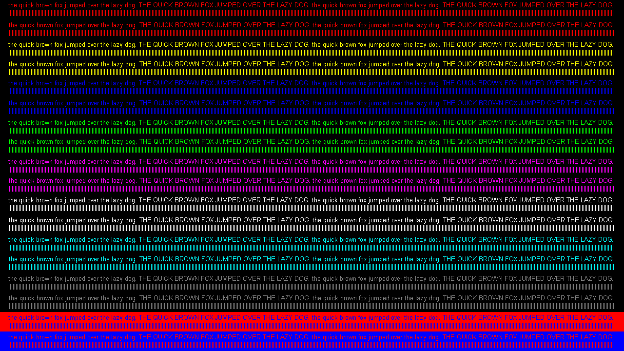
Regarding differences between labeling the HDMI input, there certainly are. I encourage you to display the rtings image in an SDR mode while switching the HDMI input mode between PC and BluRay, while keeping the output of your GPU at RGB 8 bit 60Hz. There’s not only a severe loss in sharpness of the text over the red background in the last lines, but the color of all the lines changes, being severely desaturated when the HDMI input is labeled BluRay.
When I was speaking about how HDR output is displayed with madVR , I was thinking of something else actually: you see, the GPU card will take the framebuffer content and apply a color conversion on it and a tonemap function, in order to send to the display properly encoded content. This happens based on the frame-buffer format, the gamut and tone curve info the TV exposes through its EDID, and the desired conversions picked when creating the backbuffer. I have no idea what settings madVR chooses, and if we’re not defeated from start, being impossible to us to send values encoded to the TV using whatever tone mapping we desired, instead of having the GPU apply the HDR PQ EOTF to the back-buffer content. Here is what nvidia said back in 2017:
The Siggraph video presentation:
http://on-demand.gputechconf.com/siggraph/2017/video/sig1702-thomas-true-programming-high-dynamic-range-rendering.htmlThe GTC slides (from the previous presentation, not the Siggraph one): http://on-demand.gputechconf.com/gtc/2017/presentation/s7394-tom-true-programming-for-high-dynamic-range.pdf
2019-12-23 at 16:48 #21894Regarding differences between labeling the HDMI input, there certainly are. I encourage you to display the rtings image in an SDR mode while switching the HDMI input mode between PC and BluRay
Of course you are right, but I meant “between normal labels”: not PC but any other.
2019-12-23 at 19:06 #21895@janos-toth-f, I have a question not really related to the topic: When you measure the luminance of the OLED panel with the i1D3 (with the generic CMF, not correction applied) and with the i1Pro2, do you get the same luminance? In my case, there’s a difference of about 3-4 nits, and I wonder if that’s usual.
There is always some difference between the i1Pro2 and i1d3 Y readings (sometimes it seems alarmingly big but neither instrument guarantees tight Y accuracy). In case of the C9, it was minimal.
LUMINANCE_XYZ_CDM2 “272.078819 281.941494 431.655262”
LUMINANCE_XYZ_CDM2 “267.816724 278.445695 419.893831”-
This reply was modified 6 years, 6 months ago by János Tóth F..
Attachments:
You must be logged in to view attached files.2019-12-25 at 14:39 #21940@janos-toth-f, thank you!
Indeed, you have the same kind of difference in luminance between the i1Pro2 and i1 Display Pro as I have. I have asked on avsforum in the OLED LightSpace calibration thread, and the replies were similar, there is always a difference in the luminance measured by the two. I now wonder why people say an i1Display Pro can be used by itself to calibrate and profile OLED displays, when there is such a difference in the measured luminance.
2019-12-25 at 16:35 #21941@janos-toth-f, thank you!
Indeed, you have the same kind of difference in luminance between the i1Pro2 and i1 Display Pro as I have. I have asked on avsforum in the OLED LightSpace calibration thread, and the replies were similar, there is always a difference in the luminance measured by the two. I now wonder why people say an i1Display Pro can be used by itself to calibrate and profile OLED displays, when there is such a difference in the measured luminance.
I wouldn’t neccessary call this a huge difference. And do note that the i1d3 was in “generic” spectral self-correction mode for the CCMX creation (I didn’t use my own C9 CCSS or the generic OLED EDR for these measurements).
X-Rite claims (for the i1Pro): Inter-instrument agreement: 0.4 ∆E94* average, 1.0 ∆E94* max. (no specific numbers for luminance or even general ABSOLUTE accuracy though, only inter-instrument…)
But take a look at this (a better but somewhat affordable spectro with more detailed factory specs): ColorimetryResearch CR-250 Spectrophotometer: Luminance Accuracy ±2 % Ω (Ω Measured with luminance level of 1.7 Nits (0.5 fL)2019-12-27 at 11:57 #21948In the meantime I created (a) SDR 3dlut(s) for madvr (!) after a full dcc reset, but surprisingly I can’t really see difference between the previous 3dlut + factory preset and this one
 (I’ve posted the results there, so I can edit it later.)
I created another one with the following changes (I haven’t uploaded screens and results either):
– on Display: FFPI duration: 0.5
– on Calibration:
— select 6500K WP
— tone curve: gamma 2.4, Medium speed
– the rest is at default madvr sdr presetResult:
– color temp and gamma graph are a bit better
– but the higher end of gamma (towards whites) are lower this time to 2.3 , 2.2 (the exact opposite of the previous try where they were increased): maybe enabling white level drift comp can help with this, I don’t know (it worsened the result without calibration)
– and: checking a white clipping pattern from avshd bt709 mp4 file with madvr and the resulted 3dlut, the bars are pink (!) on the image and almost the bars are visible (not just till 235)
@Josh, have you taken a look at a white clipping pattern with your 4. and 5. test cases?
And as you see, I don’t get so nicely flattened gamma as you did.2019-12-29 at 11:46 #21960Here’s another try with unity1dlut + unity3dlut for madvr SDR. (I uploaded the 2 verification results here as well.)
And I just realized that the LS guru guys for SDR 3dlut generation leave the factory 1dlut in place (!) and only upload unity 3dlut to the TV, not both.
I asked Ted about this, and that’s what he said:
– on 2018 models, an uploaded 1D LUT, even a unity 1dlut (!) adds extra processing that altering the signal and degrade the picture quality
– on 2019 models, although the problem is fixed with 1dlut, but it’s still not worth to deal with it due to the WRGB panelSo, I guess I will try next the only remaining case:
– factory 1dlut + unity 3dlut1 more thing about SDR: it seems that using BFI, at least 3secs, can achieve better result than using white level drift comp (even with short BFI), but obviously it lasts way longer.
-
This reply was modified 6 years, 6 months ago by chros.
Attachments:
You must be logged in to view attached files.2019-12-29 at 12:30 #21964I asked Ted about this, and that’s what he said:<br>
– on 2018 models, an uploaded 1D LUT, even a unity 1dlut (!) adds extra processing that altering the signal and degrade the picture quality<br>
– on 2019 models, although the problem is fixed with 1dlut, but it’s still not worth to deal with it due to the WRGB panelHere’s more info about this.
2019-12-29 at 19:54 #21970@chros, if you get weird casts on the contrast patterns (near white patches), it’s because there is clipping on some of the RGB channels. In a normal calibration, what one would do in this case would be to reduce the Contrast controls (or the RGB gain controls) while watching the white patches pattern, until the cast disappears while trying to avoid clipping the patches. However, I would have expected for the LUT to correct this.
The Calibration images in the downloads menu should have these kind of patches, btw: https://www.lightillusion.com/downloads.html
But yes, the recommended way to celebrate OLEDs is to leave the 1D LUT untouched and to only create a 3D LUT.
Ted has a LG OLED calibration guide on his website, but it does not have the latest rules on how to create LUTs: https://displaycalibrations.com/lg_2018_oled_profiling_using_lightspace.html
2019-12-29 at 21:06 #21971I forgot to say one more thing: I did not follow what you were doing, to know how you got the casts on the white patches.
If you got them after uploading a 1D LUT, then that sounds familiar. I reported this issue in a post on avsforum as soon as Calman Autocal for LG appeared, and got flak from all the Calman supporters (and got some totally bonkers attempts at explanation, too). Then I saw someone else got the same issues later. We were using AutoCal with the GPU configured for full RGB levels, the TV input set to High, and using full RGB patterns. Afterwards, Tyler from Calman came and said that the right way to calibrate with Calman was by using GPU set to full, TV input to low, and 16-255 patterns. And if you need to use the TV in High mode (for proper full range data signals when using it as a PC display), then you can switch it to that after you’re done calibrating.
Tried it that way, and indeed I got no more casts on the white patches. But when switching the TV input from Low to High, the gamma curve does change a little, it’s not the same as during calibration.
In any case, Ted mentioned on the page you linked that one gets different results between:
- a profile of the TV after uploading the 1D LUT into it
- and the profile you get if you don’t upload the 1D LUT to the TV, but instead send to the TV patches corrected with the 1D LUT
That shows the TV has some additional processing stages before or after the 1D LUT while we are not expecting them in the way we have our 1D LUT generated (we expect to have the 1D LUT and the 3D LUT applied without any extra processing in between them, or in addition to them afterwards). That’s where and why the clipping happens likely, giving those weird casts.
What’s certain is that what Ted speaks of is clearly the result of many attempts at calibrating these LG TV sets, so the final recommendations from the LS guys are likely the best methods to do the calibration.
2019-12-30 at 11:49 #21979I did not follow what you were doing, to know how you got the casts on the white patches.
Seriously?! 🙂 It’s not that complicated, everything is written on avsforum. I understnd you try to help me, but it’s not helpful if you don’t (want to) know what I’m doing. 🙂
So 1 more time: I tried to create an SDR 3dlut for madvr (!!!) not for the TV (!) while TV does the least amount of processing (hence the unity 1dlut and unity 3dlut were uploaded to the TV).
If you got them after uploading a 1D LUT … the GPU configured for full RGB levels, the TV input set to High, and using full RGB patterns.
Exactly my case, I uploaded unity 1dlut (and unity 3dlut as well).
the right way to calibrate with Calman was by using GPU set to full, TV input to low, and 16-255 patterns. And if you need to use the TV in High mode (for proper full range data signals when using it as a PC display), then you can switch it to that after you’re done calibrating
….
But when switching the TV input from Low to High, the gamma curve does change a little, it’s not the same as during calibration.😀 That’s just utter bollocks. Instead of telling: “no, it won’t work at all this way, don’t even try” etc., they tell you some bullshit, as you stated. And not just the gamma that is changed between Normal and PC mode, but colors are measured differently as well.
As I said, I have to try it with factory 1dlut + unity 3dlut, and see how it goes.
-
AuthorPosts